


The following pictures show typical screen shots of the Bartels AutoEngineer® software. The basic BAE user interface is identical on the supported platforms. However, through the User Language which is freely available with every BAE system, the features for customizing the menu layout and adding new functions virtually unlimited. We are encouraging and supporting users in adapting the menu to their special requirements. I.e., customer-specific BAE menus are commonplace...
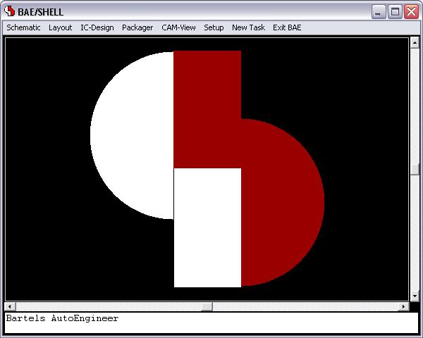
Bartels AutoEngineer Main Menu |
Figure 1 shows a screen shot from the BAE HighEnd main menu screen on Windows XP. The function starts additional processes coupled with the current process, thus allowing for inter-module communications such as cross-highlighting between the Schematic Editor and the PCB Layout Editor. The CAM View module including Gerber viewer, panelization functions and manufacturing data optimizers is provided with every AutoEngineer layout system at no additional cost. The menu below also shows the function for activating the optional IC/ASIC Design system:
Bartels AutoEngineer Schematic Capture |
Figure 2 shows a typical Schematic Capture session. The toolbar at the left provides buttons for frequently used display and file functions, design view management facilities, and a feature for automatic part attribute settings, all of which is designed and can be fully customized through User Language. Please note the resistor attributes and the bus connection to the processor IC in the schematic plan. The system automatically connects the individual bus lines based on the logical library description:
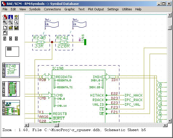
Figure 2: Bartels AutoEngineer Schematic Capture
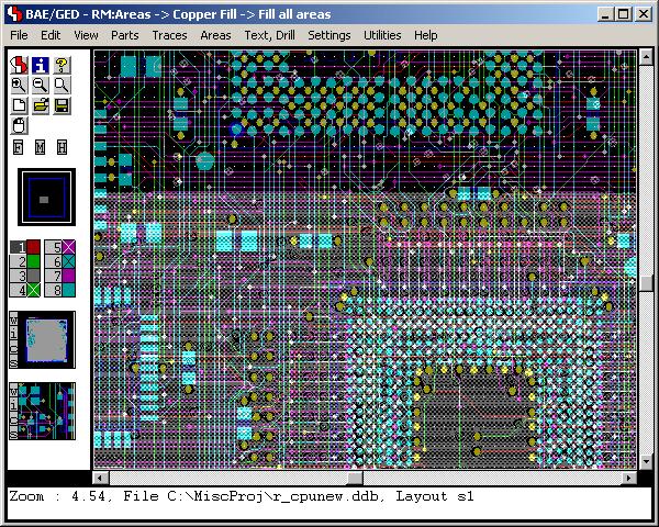
Bartels AutoEngineer PCB Layout |
Figure 3 shows a typical PCB Layout Editor window. The PCB layout displayed shows a mixture of possible design options, such as the use of surface mounted devices (SMDs), curved traces, negative split power planes, positive copper pour areas, irregular pad and copper shapes, etc. The DRC is able to handle all these online and in real time, as it is based on an incremental technology which also allows for multi-step . The toolbar on the lefthand side is designed with User Language and provides design view management facilities and buttons for frequently used display and file access functions:
Figure 3: Bartels AutoEngineer PCB Layout
Bartels AutoEngineer ASIC/IC Design |
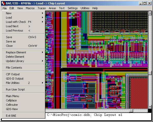
An IC design module including real-time mask connectivity, GDS2 I/O, Standard Cell Placement with intelligent algorithms as well as routing using the Bartels AutoEngineer in its IC design version is available as an option. Figure 4 shows a typical IC mask layout (Chip Editor) session.
(http://www.bme.ie/bae/baedoc/baescreenshots_en.htm)